Designing a line sensor array PCB
The sensor array used on our line following buggy
Introduction
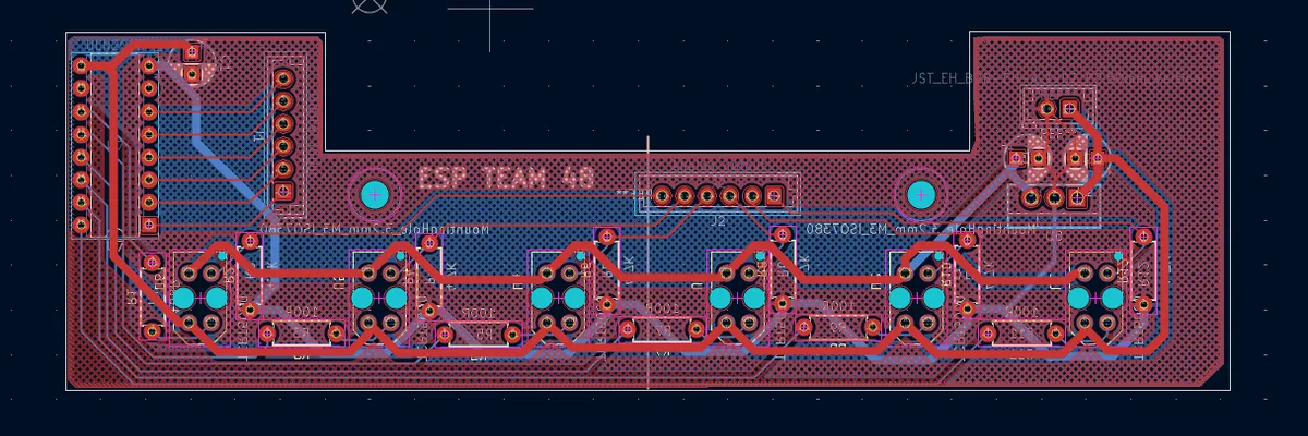
For our 2nd year embedded systems project we designed a line following buggy. The track used is a matt black track with white tape down the middle and the buggy needs to follow the line around the track. We used infrared TCRT5000 sensors to track the line, with a really simple PCB to arrange the sensors in an array. This article provides some detail on the design. In the main esp48 page the pcb is hidden under the spoiler (designed for aerodynamic purposes of course)
Basic principle
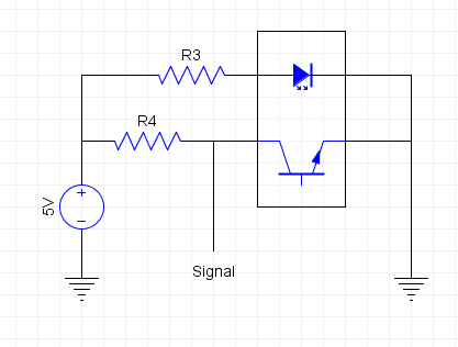
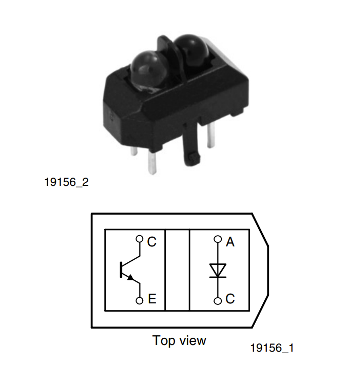
The sensor module consists of an infrared emitter and a phototransistor. The sensor outputs a voltage proportional to the light reflected. The white surface being more reflective outputs a lower reading than the black surface, or vice versa with the resistor and output signal on the low side as seen later. Changing R3 and R4 varies the light intensity of the IR emitter and the phototransistor sensitivity respectively.
Testing for the design
To test out the sensor as it moves from one side of the white line to the other, we initially had a setup with a ruler and a multimeter, measuring the output at each position. This was intended to allow us to determine the best height and separation for our sensor array.
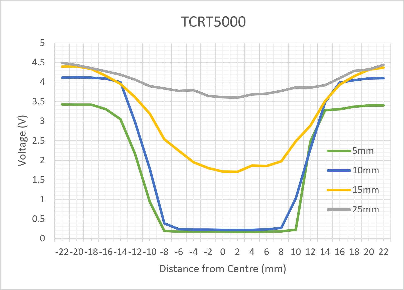
Whilst this did show the behaviour of the sensor as it passed over the line, it was time consuming and prone to human error. Another team member automated the test setup using a stepper motor and logging script, which allowed us to see the trends far more clearly and with different resistor values on the phototransistor side. (At this point we had realised that the nucleo’s ADC saturates at 3.3V and decided to use a regulator to maximise the range of readings)
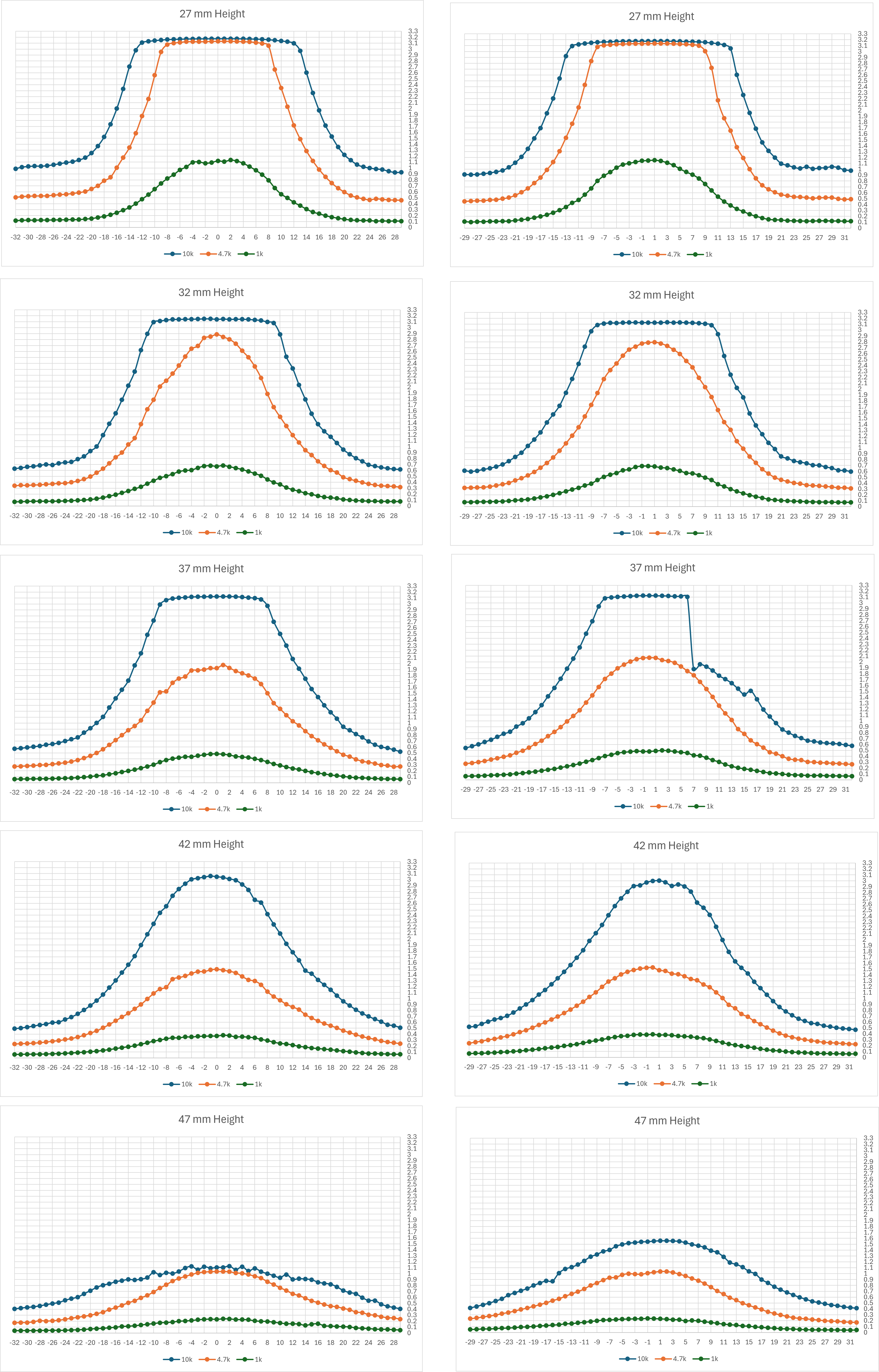
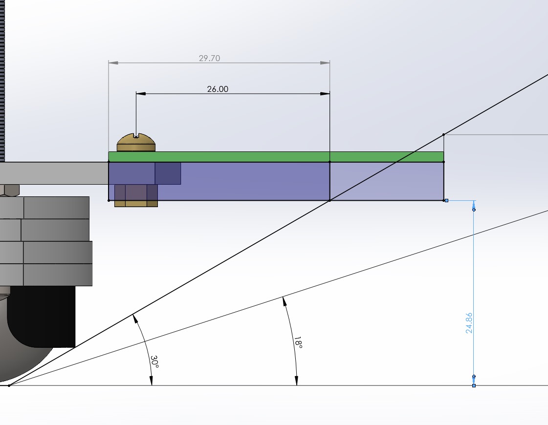
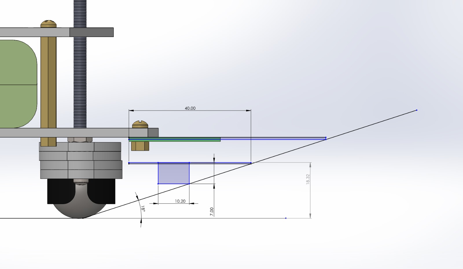
We settled on a a 4k7 ohm resistor to maximise the range of the ADC without saturating the sensor. We also decided that 20mm would be a good separation to allow for the curves of the 2 sensors adjacent to the line to be used to determine the centre. 6 sensors overall due to the number of analog pins that were available on the nucleo. The optimal height was slightly more complicated as the track involves several inclines, so having the array too close to the ground would mean it would collide with the track. We tried to make the PCB as narrow as possible to allow for a lower height at steeper inclines.
The final PCB
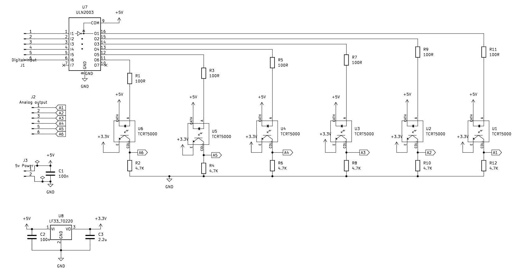
The final circuit included the 6 sensors, a 3v3 regulator, connectors and a darlington array. The darlington array was used to allow for the emitters to be driven from the power supply rather than the nucleo’s digital outputs. We also considered using it to switch each LED on and off before and after sampling to reduce crosstalk between the sensors, but it didn’t have much of an impact.