Electronics Architecture of a Forumla Student Car (Part I - Data Architecture)
The design process behind the data architecture for the team's first EV
Introduction
When we first began work on the auxillary electronics team we had no idea where to begin. As the year progressed we started to get a better idea of what the electronic architecture on the EV should look like. Since I’ve not actually done a proper write up on this I thought it would be nice idea to document the process. For part I, I want focus primarily on the data architecture between sensors and actuators on the car.
On a side note I use the terms auxiliary and LV electronics interchangably. Although they don’t always mean the same thing, in this context it means anything not related to the HV battery. I find the title “auxiliary” confuses most people without a lengthy explanation about what it covers.
Where to start
The scope of the auxiliary team covered two main remits:
- Essentials for the car to run (either for functionality or through adherence to the rules)
- Any “nice to haves” which improve the overall performance of the car
The first big decision we faced was deciding where to draw line between these two domains.
Considering that the motor and motor controller had already been purchased, functionally all we needed was an analog pedal position sensor to get the motors spinning. Even the logic for dual redundancy and plausibility checks on the acceleration pedal sensors can be programmed into the DTI HV500 without any additional hardware and purely using it’s IO channels. Same thing for R2D input and LED indicator + buzzer output. You could even connect digital outputs to control shutdown circuit coils (tripping at set error conditions) and implement pre-charge/discharge completely through the motor controller as well but the rules tend to be quite strict on having a standalone analog circuits for them.
Whilst that would have been the easy solution where the motor controller essentially works in the same way as a plug and play ECU for a petrol kart, it doesn’t feel like “real” engineering to have all the programmable logic configured on a consumer GUI.
Distributed logic
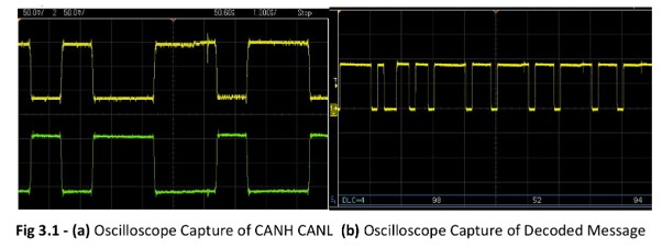
As the price of microcontrollers (and the time taken to programme them) declines, the way that most vehicles (cars, karts, bikes) work nowadays is using a network of dozens (hundreds) of digital nodes that can communicate with sensors and actuators on a common bus. This is typically done over a protocol called CAN (controlled area network), although ethernet is becoming increasing popular due to the throughput that many ADAS systems require.
There are many resources online about CAN and why it’s considered to be standard in the automotive industry, but in summary:
- Analog signals experience noise, the closer to the source they are sampled the less noise you will be picking up on. Using a digital protocol means you are sending the encoded data
- Digital signals also experience noise, using a differential pair means the noise cancels out so you the bits are less likely to distort
- CAN has built in error checking so you can catch distorted packets
- Bus topology means nodes can speak to one another without needed a gateway device
- ID based arbitration means you can configure IDs to reflect priority (eg. Battery is on fire ranks higher than radio volume is 17)
FS scale
When applying this architecture a formula student car we can also split devices into actuators and sensors. Based on their priority we can assign IDs and based on their location we can group sensors and actuators into regional nodes.
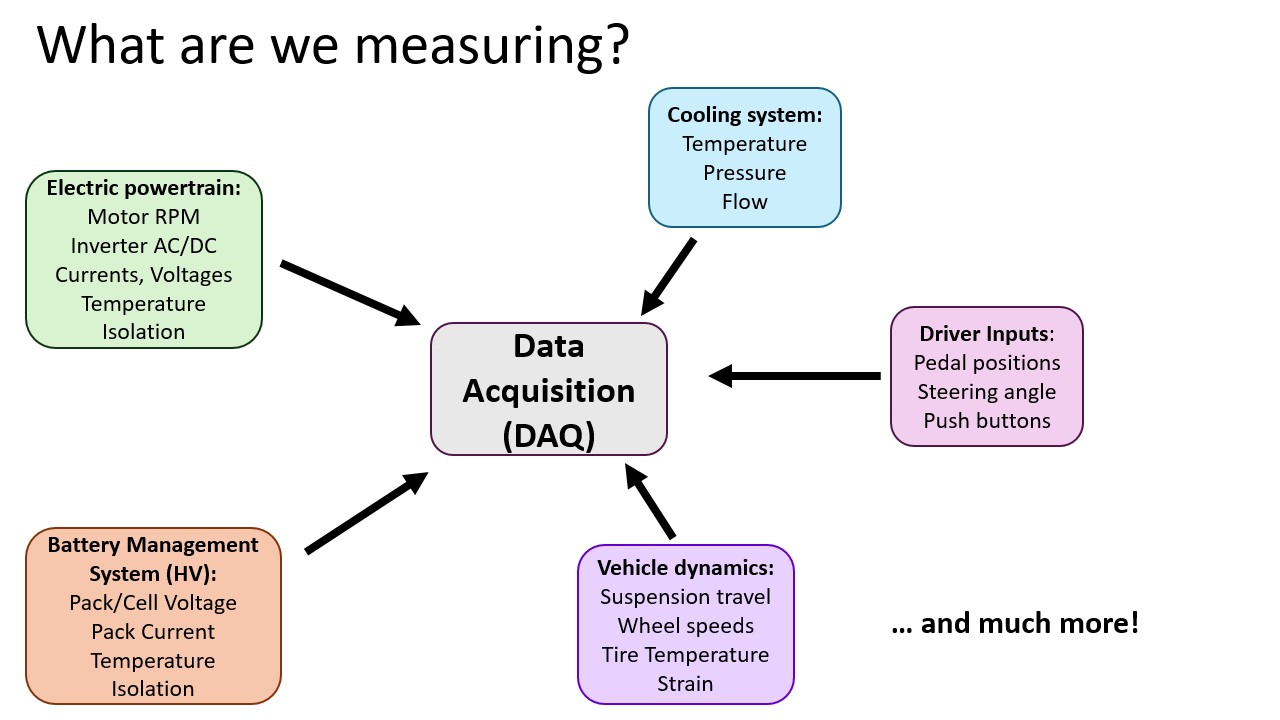
Although not all the data collected will stricty be used for control, validating the design of all other systems requires logging the data to evaluate the performance.
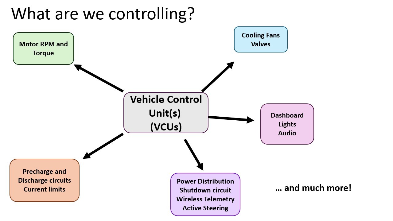
Whilst the initial setup for this is a bigger challenge than the simple option mentioned previously, with a distrubted nodal architecture adding sensors or actuators as each of sub-systems requirements increases can be straightforward and simple. You don’t need to redesign the loom any time you want to add or remove something, issues can be easily isolated making debugging far easier and will allow for future integration of a driverless system.
EV Concept Class 23/24
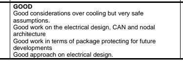
When I presented this to the judges in silverstone for our concept class EV this architecture was highlighted as one of the positives. Some of the feedback they mentioned afterwards was that some high level diagrams to show how the system fits together would have helped support the presentation.
Puting it to practice
Although we didn’t get far during that year in building much of the hardware for this system beyond a few breakouts due to some logistical challanges, several members of the team carried the concept into their individual design projects. For example, I designed a wireless CAN bridge to stream telemetry data, another member worked on a custom VCU, another on CAN-based dash and the following year another on CAN IO boards.
Rest of the series
Stay tuned for follow up blogs on the rest of the electronics design :)