Integrating a hall-effect angle encoder into a robotic joint
Using a AS5600L hall-effect sensor and an embedded magnet to detect the angle between the rails and brush motor housing on GR8BOT
Introduction
GR8BOT uses a pin-slot mechanism to adjust the angle of the brushes to match the angle of the solar panel. To do this autonmously is uses an array of proximity sensor to calculate the target angle, pulleys to adjust the angle and angle encoders to provide feedback fo closed loop control.
Integrated housing
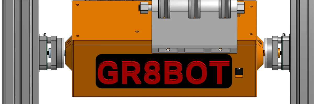
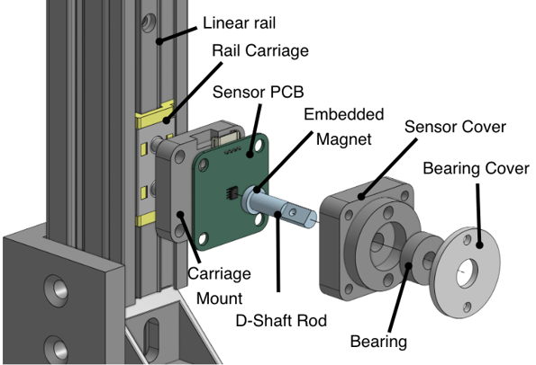
Although there are many off-the-shelf hall effect sensor modules available I wanted to experiment with designing a low cost alternative that could be integrated into the parts we were designing. Since much of the components on the robot were 3D printed we had alot of freedom when it came it came to the physical design. The diagram below shows the hall effect sensor on the rail side mount, with the magnet embedded into shaft that couples to brush motor box (as shown in the header.)
Testing with a stepper
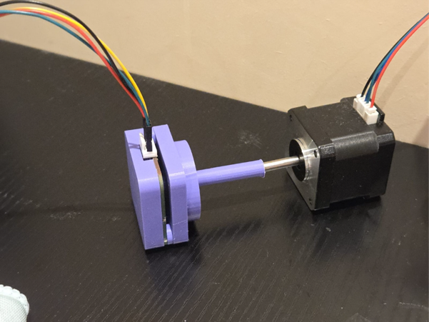
To test the how accurately the sensor was in measuring the angle I printed an alternative shaft that could couple to a stepper motor. The sensor angle readings and the step count from the motor were logged using a python script. The arrangment can be seen here:
To get some useful insights from the data, the measured angle (using the sensor) is subtracted from expected angle (using the step count), which gives the angle error. This was done over 3 cycles for both sensors and ploted as seen below
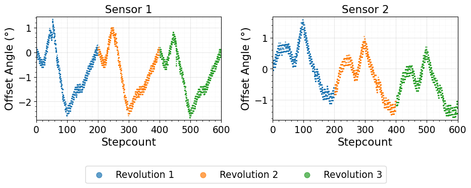
Although the results showed a consistent profile across all 3 cycles (with a greater drift in sensor 2), there is a non linearity error under ± 2 on both sensors. Looking at the application sheet we can find some explanation as to what might be causing this systemetic error.
Horizontal Misalignment
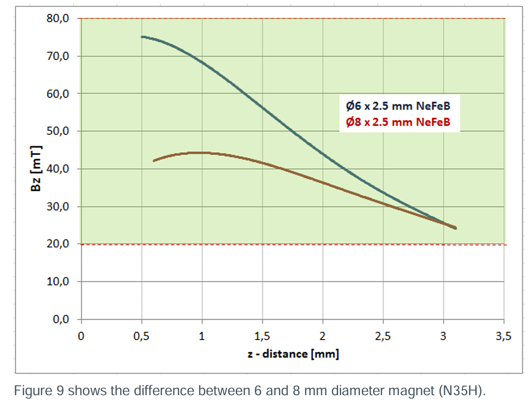
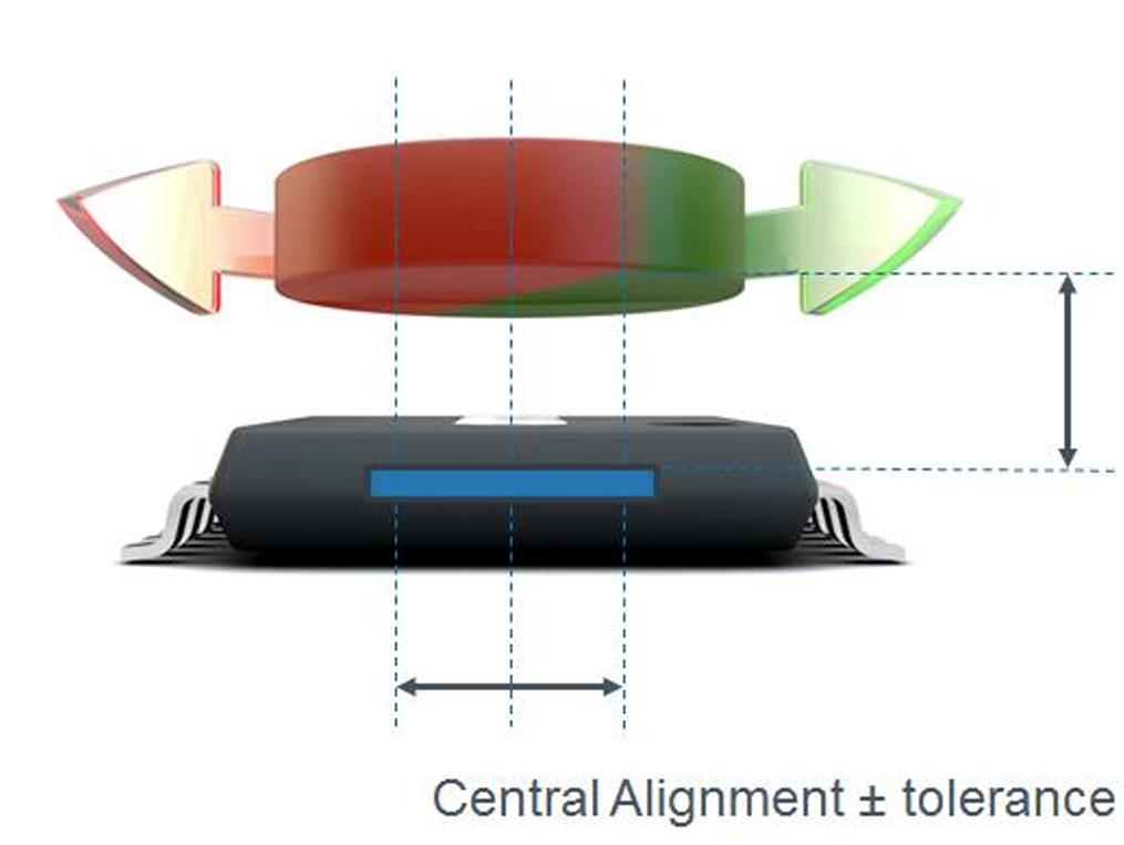
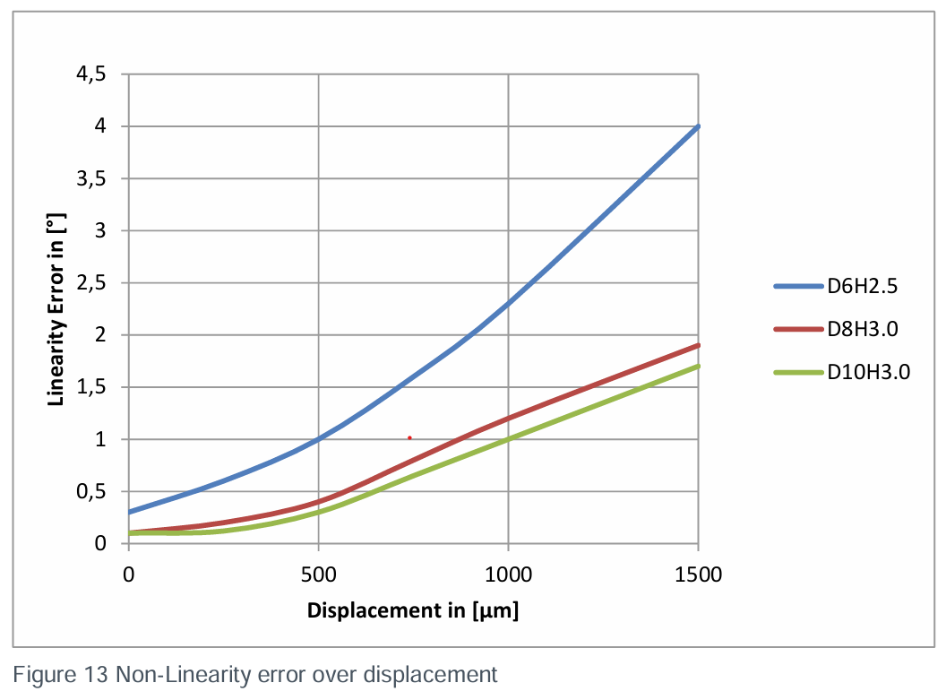
The first and most likely cause is a horizontal misalignment between the sensor and the magnet. According to the results provided by ams in the application note even a misalignment of 1mm can introduce a non-linearity error greater than 2 (6mm magnet was used). Considering that the sensor was soldered on by hand and the tolerances added to the 3D printed assembly this offset is likely the primary cause.
Magnet Tilt Angle
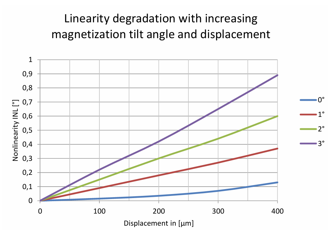
The other possible cause of error is a skew in the angle of magnet relative to the sensor where the magnet is non fully parrallel to the sensor. This can either be caused by a non uniform magnetisation profile on the actual magnet, or a skew in the mouting position, which introduces a non-linearity error.
Airgap
If the airgap between the sensor and the magnet is too large, the magnetic flux density that the sensor picks up is too weak leading to skewed results. The raw flux value can be read over I2C and sat within the expected range, so I think it’s less likely to have been the primary cause.